
Mixed Scale Controller DIY DRO Kit is designed to simplify the build process of the "Mixed Scale" DRO controller. As the name suggests, this version of the controller comes as a do-it-yourself kit that consists of a bare printed circuit board, MSP430 microcontroller pre-programmed with the "Mixed Scale" firmware, BlueTooth transceiver, and all of the necessary parts to build the voltage shifter circuit. The board is primarily designed to run the Mixed Scale firmware and interface with 1.5V and/or 3.3V scales and calipers, but can be easily tweaked to work with quadrature encoders instead.
Compared to building a controller on a breadboard, the main benefit of this kit is the professionally designed and fabricated circuit board. Quite obviously, it's much more convenient to assemble a controller on a pre-made circuit board. More importantly, though, the end result will likely be much more stable and reliable, since the PCB is carefully laid out to minimize the effects of noise.
 |
| Finished Mixed Scale DRO Controller |
Controller Features
- Provides input for up to four axis, directional tachometer and touch probe.
- Supported protocols include:
- Sylvac Protocol (48-bit) used by the common "Chinese" scales
- 21-bit protocol used by Shahe, iGaging DigiMag remote DRO, and AccuRemote scales
- BIN6 protocol used by most Inexpensive digital calipers
- Each scale input can be independently configured to use either 3.3V or 1.6V power supply
- Clock for iGaging scales can be provided to each scale individually using a jumper setting.
Please note, the controller can't be used with a mix of capacitive and quadrature DRO scales at the same time. The board is pin-compatible with quadrature firmware, so if at a later time you decided to upgrade the scales, the chip can be re-flashed with quadrature firmware. Since the board doesn't have a 5V regulator, a small hardware mod is required as well: two resistors need to be removed and 5V from a power supply will need to be connected to a pin so it can be routed to the scales.
What's Included
- Professionally fabricated PCB
- Pre-programmed MSP430G2553 microcontroller (with a socket).
- HC-05 BlueTooth transceiver
- 3.3V low-dropout voltage regulator
- LM339 comparators (2)
- 47 KOhm resistors (17 )
- 4.7 KOhm resistors (8)
- 220 Ohm resistors (5)
- 0.1 uF ceramic capacitors (9)
- 100 uF electrolytic capacitors (3)
- 2.1mm x 5mm power jack
- 2x3 pin headers (4)
- 2x4 pin header
- LEDs (1 each, Red, Green, Amber)
You will need to provide a power supply that can provide between 5V and 13V, and a plastic enclosure.
Warnings
- Calipers and Sylvac-type scales can easily be damaged by 3.3V supply, so make sure the jumper setting is correct before connecting the scales.
- Probe and tachometer pins are connected directly to MSP430, therefore if voltage over 3.6V is ever applied to them, even for a brief moment, the microcontroller will be permanently damaged.
- The frame of iGaging Remote DRO scales is connected to the ground, while calipers and Sylvac scales are connected to Vcc. If you intend to mix the two types of scales, ensure that they are insulated from each other or you will blow up the voltage regulator on the board, and possibly explode the electrolytic capacitors.
- Voltage regulator can be pretty hot and burn you, especially if the input voltage is close to 13V. If available, use a power supply that is as close to 5V as possible to keep the regulator cool.
Mechanical Dimensions

Pin Functions
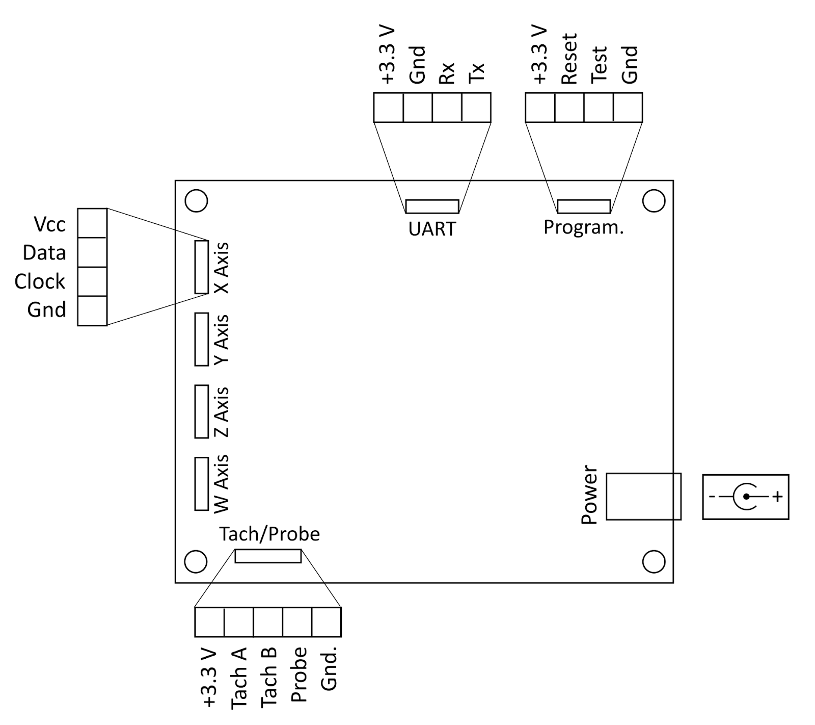
Scale Inputs
Scale inputs are located along the left edge of the board (as shown in the picture). The pins are labeled +, D, and C for Vcc, Data and Clock respectively. The last [unmarked] pin is Ground.
Tachometer Input
The board can work with directional (quadrature) and non-directional tachometer input. The pins are connected directly to the microcontroller and have internal pull-down resistors enabled.
Warning: These pins are not buffered, so care should be taken to not exceed the 3.6V maximum rating for the microcontroller.
Touch Probe Input
Touch probe pin is located on the same header as the tachometer input. The controller supports normally open and normally closed probes, which will be detected at the startup.
UART Output
UART output header is located on the top edge of the board (close to the middle). The pin sequence matches that of a standard 4-pin HC-05 module, so one can be soldered directly into the board.
In-Circuit Programming Header
This header, located to the right of the UART header, can be used to program the microcontroller using either the MSP430 Launchpad or a dedicated ICP device.
Jumper Settings

Scale Voltage Selection
Each scale input can provide either 3.3V or 1.5V to the scales. The voltage is selected using a jumper setting on the appropriate header as shown below. The same settings provides a reference voltage to the comparator.

Resistor Selector
The board supports different input modes (open drain, line driver and push-pull) that require either pullup or pulldown resistor, which can be configured using the resistor selector jumper setting for each scale individually.
For most capacitive scales, except iGaging AbsoluteDRO+, pull-down resistors should be used; additionally pull-up mode might be useful for rotary encoders, etc.

Please note, using pull-up resistor for 1.5V scales will damage them, since the resistor pulls the line up to 3.3V.
Scale Clock
iGaging DigiMag Remote DROand AccuRemote scales require external clock signal that is provided by the microcontroller. The clock signal can be connected to each scale using the "Scale clock" header. To provide clock signal to a scale, install a jumper on the corresponding pair of pins.
Make sure the clock is disconnected when 1.5V scales are used, or the scale will be damaged by the 3.3V signal coming from the controller.
LEDs
The board has three LEDs that indicate its state. Their functions, from left to right are:
- Touch Probe Activated - the LED will be lit when the touch probe is activated.
- Status/Heartbeat - the LED indicates the status of the board. During startup initialization the LED will blink rapidly for about one second while the board is detecting scale protocols and probe state. After that it will blink at 1HZ rate (once per second)
- Power - the LED will be lit when the board is powered on
Power Supply
The kit comes with a standard 2.1mm x 5mm power jack, same as many of the Arduino boards. The on-board voltage regulator can accept from 5V to 13V and convert it to regulated 3.3V. It's better to go with lower input voltage to keep the regulator cool, otherwise a heat sink might be need.
If you indend to use the kit with Quadrature scales, the power supply should be regulated. Most scales on the market can handle a range of voltages from 5v and up (check the manual for your particular scale).
Conclusion
The Mixed Scale TouchDRO controller kit is a versatile and cost-effective do-it-yourself DRO controller that provides a lot of flexibility. By default it works with most capacitive scales and calipers, providing reasonable refresh rate and excellent noise immunity, and with a few tweaks can read quadrature scales. Compared to the same circuit built on a prototyping board, the kit offers much better resistance to interference, reliability and convenience. At the same time the cost of the kit is not that much higher than what you'd spend buying the components separately, especially given that the kit comes with name-brand parts procured from reputable suppliers.
Hi Yuri
ReplyDeleteI have ordered one of these kits.
I have 4 1.5v calipers that I intend to attach to it.
The Tacho sensor I want to use is a Hall effect gear tooth sensor that needs 5v.
I was thinking of attaching a 5v rotary encoder to the top slide and making a board using the Launchpad.
You say a 5v to 13v power supply, what amps should I be looking for?
Ken
Ken,
DeleteThe whole board uses on the order of 50 mA, so any power supply should be good. You want to get as close to 5V as possible - that way the voltage regulator will not have to work as hard (i.e. will run cooler).
Also, make sure the MCU doesn't see 5V or it will burn out in a fraction of a second.
Thanks Yuri.
ReplyDeleteI am sat here with the soldering iron waiting for the postman.
Ken
After a few glitches with the post office, I have the kit, and it looks great. I know you're working on instructions, but I'm itching to get started ASAP, and I have two questions. First as a noob, I figured out that the 3 circles with flats are the LEDs (which have corresponding flats on their tiny flanges, so we get the polarity correct), but I want to confirm that with the electrolytic capacitors (upright cylinder shaped), that the stripe on the side should align with the thickened line on the side of the circle on the PCB.
ReplyDeleteThe second question isn't noob-ish: which color led goes where?
Thanks very much for all this great work!
Tom
Tom,
DeleteYou are correct about LED and capacitor orientation.
Led functions are described in the LEDs section above. You can use whatever color you want to use for each function.
Thank you
Yuriy
Yuri - thanks! A couple more questions:
Delete- Mounting the HC-05 Bluetooth module: It looks like the two outermost pin aren't used. On the board's UART pins, "+" connects to the module's "VCC", "-" to "GND", "Rx" to the module's "TXD" and "Tx" to "RXD". Is that correct?
- I'm using the Sparkfun Mini USB breakout boards. I'm looking at your post about modifying the HP Launchpad, and it looks to me like you connect "VCC" on the breakout to "+" on your board, and "GND" on the breakout to the unlabeled pad. Is it "C" (for clock) on the board to "D-" on the breakout, and "D" on your board to "D+" on the breakout?
Tom,
DeleteCorrect, if you're soldering the BT module into the board, you can cut the unused pins.
I don't remember the pinout for D+/D- off the top of my head; you can try both ways and whichever way gives you a reading is correct :)
Hi Yuri
ReplyDeleteKit arrived safely in the U.K.today.
Ken
Nice to know. Let me know how the build goes.
DeleteThank you
Hi Yuri,
Deletehave completed my build and it works fine one of the scales i have is lockinging the hartbeat led on i think the scale i have is not compatable i am looking for a new scale to try and confirm it will be compatabe.
thanks ken
This comment has been removed by the author.
ReplyDeleteHi Yuri,
ReplyDeletegot my pcb's yesterday from customs office (hamburg/germany). they are looking very nice.
thanks
Stephan
Hi Yuri,
ReplyDeletePlease can you explain what I would need to do to make this board work with Quadrature Scales?
The reason I plan to use the mixed scale PCB instead of the quadrature PCB is that I currently only have two quadrature scales and I'm not sure I will purchase the same for the Z axis and quill feed on my Bridgeport in the future.
Regards
Mark
Have you published a cad drawing of the board yet? I'd like to design an enclosure.
ReplyDeleteThanks!
Even just the board dimensions and hole to hole dimensions would be enough to get an enclosure done.
ReplyDeleteThanks!
Added drawing above.
DeleteThanks! I'll publish the enclosure in the next day or two.
DeleteHello,
ReplyDeleteAdafruit Micro USB Breakout board lists pins as
VCC
D-
D+
ID
GND
Which four pins are used on the USB pins on the board?
I can assume VCC=VCC and GND=GND
Other than that, I received the board and components and all is weel. Lots of room for soldering. Piece of cake to build it up.
Thanks
I seem to have figured it out.
DeletePin1=VCC
Pin2(D)=D+
Pin3(C)=D-
Pin4=GND
I have a working DRO, bench testing.
When I hook up either a PL-2303 or FTDI USB to serial board to my tablet, start DRO, then click 'Connect', I get the message 'Unfortunately, DRO has stopped' and it vanishes.
ReplyDeleteAny ideas?
Hi Yuri,
ReplyDeleteI am adapting the board for quadratures. You mention in the controller feature section, that two resistors need to be removed and a wire (trace) needs to be added. Would you please be so kind to provide more details. Thank you in advance.
Sincerely,
Walter
Hi,
ReplyDeleteI made a 3D printable enclosure for this board:
http://www.thingiverse.com/thing:1833576
It use adafruit micro usb breakout.
Source files are in if you need to add stuff.
Sincerely
Max
Hello,
ReplyDeleteI'm trying to have a tach using the keyes hall effect sensor. It says +5 in but should work with 3.7V
Can I draw the 3.7v from pin one of the tach header? Ri ght now I have pin 1 supplying VCC, pin 2 as signal and pin 5 as ground but am only getting a dim light on my Keyes LED. If I switch the wires around on the Keyes Hall effect sensor I can get a full lit LED but still no signal back to the tach.
I have the same results on two different sensor boards.
Any help is appreciated
Is there a recommended enclosure?
ReplyDeleteYuriy, I bought one of these kits a few months ago and just started to assemble it. I realized that the MSP430G2553 is missing, not your fault.
ReplyDeleteCan I buy a new programmed one from you? If so let me how and much and I'll get one ordered.
Thanks George
George,
DeleteReplacement MCU is in the mail. You should get it in a day or two.
Regards
Yuriy
Wow! Now that's service. I can't thank you enough.
DeleteGeorge
Yuriy,
ReplyDeleteThe chips came today. Now I can finish!
Thank you so much for the help.
George
Yuriy; I have finished assembly of mixed scale DRO. I had trouble pairing with another tablet and afraid I might have done something wrong by touching the switch on the BT transmitter. I have a new tablet that says it is paired but the light on the HC-05 flashes extremely rapid, doesn't slow down. The touch DRO says it is connected but I get no readings off any of the I Gaging dro's. I am using non absolute gages. I also switched feeds on the Data and Clock to no avail. Please Help.
ReplyDeleteHi yuriy,
ReplyDeleteI bought the mixed scale kit a while back but have now decided to try some magnetic quadrature scales. Could you tell me how to order and pay for a new micro with the quadrature firmware shipped to Australia?
Regards,
Bob Dring, Sydney
Yuriy,
ReplyDeleteI bought the mixed scale kit and just received it. Being relatively new to electronics assembly, I was hoping there would be some instructions in the kit. I see that there are instructions for the MSP430 Launchpad versions but I can't find anything for the DIY Mixed kit. Do you have a schematic or some basic instructions to get me started?
Thanks.
David,
DeleteSorry about that. I accidentally removed the "Build" link. Here is the page: http://www.yuriystoys.com/2016/04/diy-dro-kit-assembly-instructions.html.
Thank you
Yuriy
Yuriy,
ReplyDeleteThanks. That did the trick. Assembled the board, tested, and hooked up to my tablet. Now I'm going to connect the scales but have read so much about the vcc being connected to the frame of the scale that I'm not sure how to wire them up. It looks like I can just wire the scale directly to the board. Is this the case or do I need to power them with an external source? I have three of the "Chinese" scales from LMS.
You can (and should) power them from the board, but you need to make sure that machine ground is not connected to the controller board ground. To be safe I'd find an old-style heavy unregulated wall wart. It will isolate the controller from the mains ground.
DeleteYuriy,
ReplyDeleteNot sure where you find the time. Thanks for the answer. I've hooked up a couple of the scales and everything is working. Is it normal to lose readings across the span of the scale? For instance my Z is 12". If I zero the scale and the DRO and check the scale to DRO reading at each inch mark I lose between 0.001 and 0.002 per inch so I'm about 12 to 14 mils by then time I reach the full span. Outside of that, your product is pretty cool. Can wait to hook it all up to the mill and make chips.
Thanks again for all your help!!!
David,
Delete1.You're welcome
2.You need to calibrate the scales. There is a video on my youtube channel on scale calibration: https://www.youtube.com/watch?v=ngX0G0Z-02s
I try to respond to questions as much as I can. This is a good feedback loop ...
Regards
Yuriy
Yuriy,
ReplyDeleteAgain, thanks. Last question and I swear I'll leave you alone. Prior to finding your product, I bought a MachTach so I would at least have spindle speed. Since you have a tach input it makes sense to use it instead of the MachTach but I'm not sure how to wire up the MacTach emitter/receiver to your board. Seem like I can power the positive side of emitter/receiver to the +3.3V, the - of the emitter to the Gnd, and wire the - of the receiver to the Tach A input? Will that work? Is the 3.3V supply limited so it won't burn out the emitter?
Thanks.
Yuriy, Great product. I just purchased the mixed scale PCB kit. I can't wait to build it and go DRO. Q: I have seen and keep finding Saili and or Yescom branded scales at the lower end of the scale pricing in all the usual places for sale. Are you familiar with these ? Are they "basic" Chinese scales or similar to absolute reading iGaging ones ? Thanks !!
ReplyDeleteHi Yuriy,
ReplyDeleteReceived kit a while. Just complete assembled it this week. Started to test run it. Apply 12V to main board one led lit up, the next one flashing. Led on BT also flashing. Launch App hit the connect button saw no connection. I did not hook up the scale at this time thinking I can do connection when all else is running. Have tried short press and long press of button on HC-05 with no luck. At this time I noticed all pins of uC were inserted in dip socket except the ground pin. Remove 12V to correct the insertion. That didn't fix the problem. What is your advice?
Regards
YK Chan
YK,
ReplyDeletePlease take a look at this:
http://www.yuriystoys.com/2013/07/troubleshooting-common-dro-connection.html
Thank you
Yuriy
Hi,
ReplyDeleteAre you willing to share the schematics and gerber files for this PCB?
Best regards,
Christian
Hey Yuri,
ReplyDeleteAre these available shipping to Canada?
-Ritchie.
Ritchie,
DeleteYes, they are. Shipping is calculated at the checkout and is usually $14-$15 to Canada.
Thank you
Yuriy
Are these still available to buy? I can't seem to find them.
ReplyDeleteHi Yuri
ReplyDeleteAre these still available to buy?
Any idea about shipping cost to South Africa?
Thanks
Willie Jacobs